2CH Channel Optocoupler Isolation Relay Module 5V/12V/24V SCM PLC Signal Amplifier Board
Tax included.
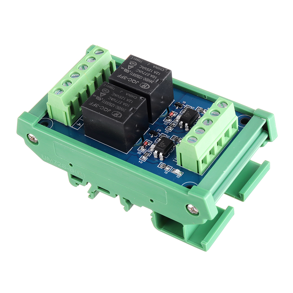
Structural Features:
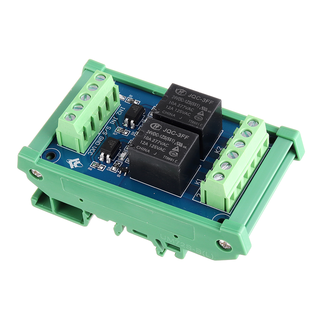
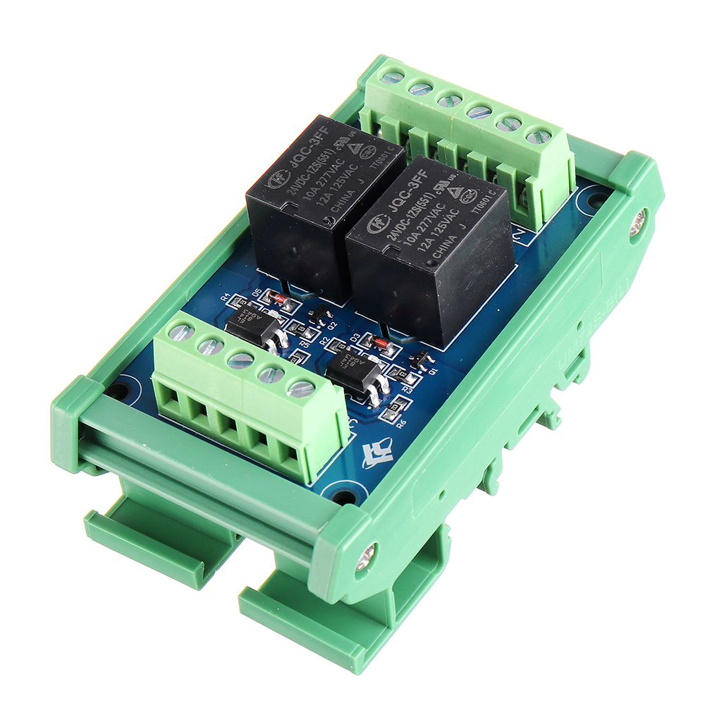
1. Use Hongfa relay, stable and reliable performance;
2. Compatible with two input modes of positive control and negative control;
3. Each channel has an LED action indicator for a more intuitive understanding of product performance;
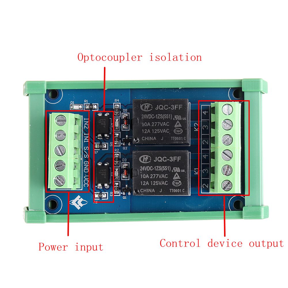
4. Each channel adopts optocoupler isolation to enhance anti-interference performance and isolation performance;
5. At the same time, the power supply and the "IN" control terminal are independently controlled;
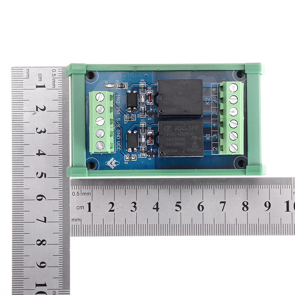
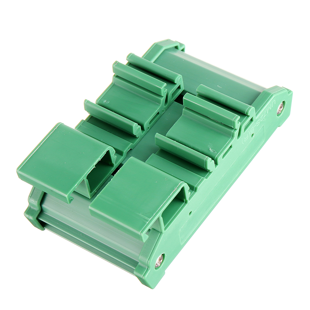
6. The module adopts the standard "DIN" rail-type installation design, which is convenient and quick to install, firm and stable.
Technical Parameters:
1. Trigger signal: DC5V / 12 / 24V (Optional)
2. Each trigger signal current: 5mA
3. Power supply voltage: DC5V / 12 / 24V
4. Each coil current: 18.8mA
5. Contact type: one normally open and one normally closed (single pole)
6. Maximum load current of each contact: 10A
7. Action time: below 12ms
8. Reset time: less than 4ms
9. Maximum switching frequency: 18000 times / hour
10. Mechanical life: more than 20 million times
11. Relay installation: plug-in type (No)
12: Module installation method: DIN standard rail installation
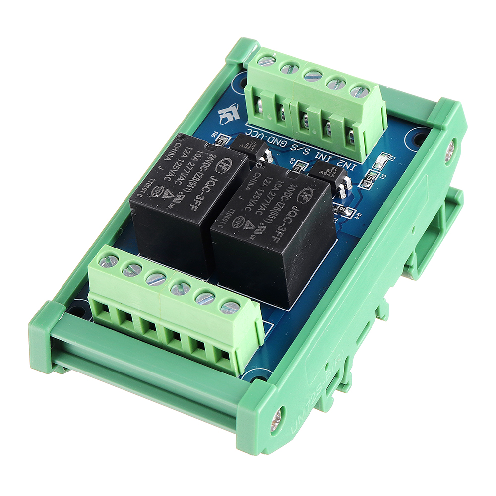
Positive control wiring introduction:
1. Power input terminal:
VCC is connected to the positive voltage, GND is connected to the negative voltage, and S / S is connected to the negative voltage
IN1, IN2 are connected to positive voltage control, IN1 controls KI terminal, IN2 controls K2 terminal
2. Control device output:
The output terminal is clearly marked with 234, 3 is a common point, 2 is normally open, and 4 is normally closed. K1, K2 means two relays work.
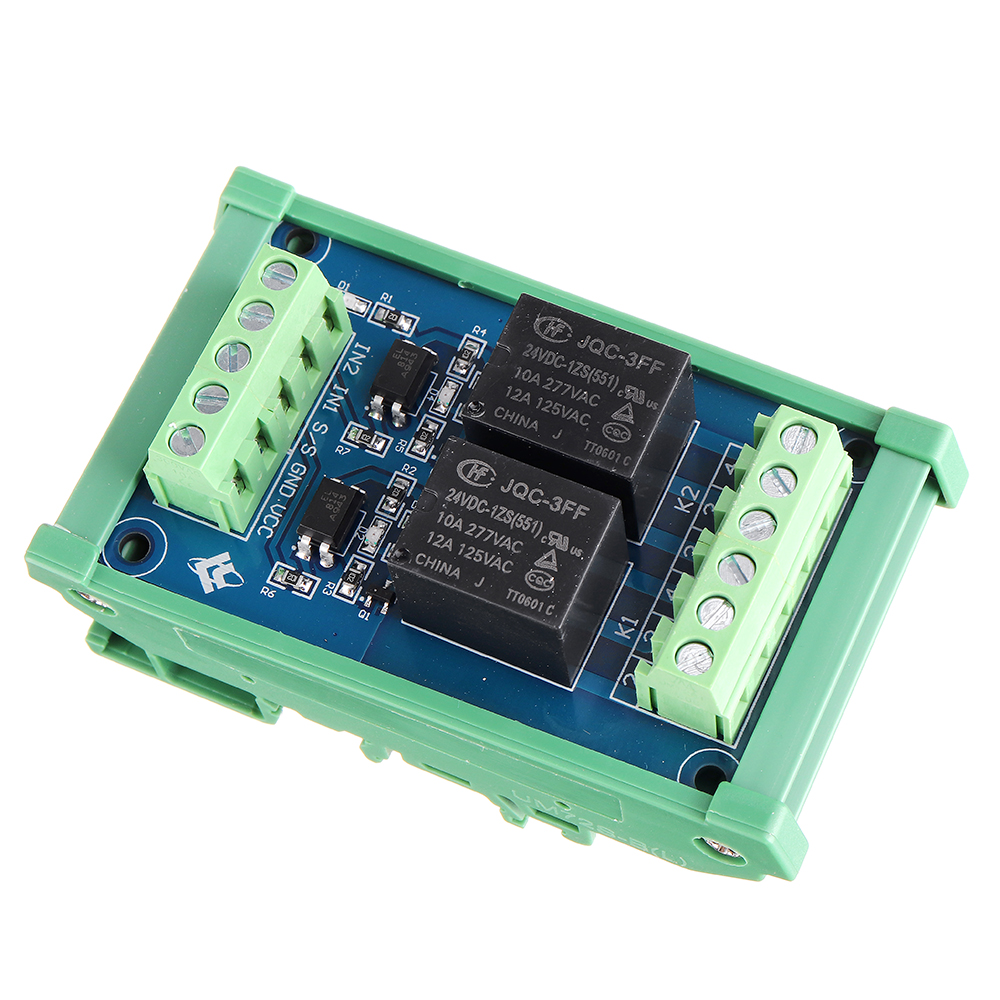
Negative control wiring introduction:
1. Power input terminal:
VCC is connected to the positive voltage, GND is connected to the negative voltage, and S / S is connected to the positive voltage
IN1, IN2 are connected to negative voltage control, IN1 controls KI terminal, IN2 controls K2 terminal
2. Control device output:
The output terminal is clearly marked with 234, 3 is a common point, 2 is normally open, and 4 is normally closed. KI, K2 means two relays work.
Package includes:
1 x Relay board
Package includes:
1 x Relay board