CC2530F256RHAR cc2530 Module Serial Port Transparent Transmission with ZB600 Development Board Kit
Tax included.
Note:
At least two CC2530 modules are needed to realize Z1gBee networking, this product contains only one.
Two methods can be used:
Application method: (The bottom layer is implemented by the board, you only do the application)
Use the firmware associated with the board. In this way, the board is a Z1gBee wireless serial port module, the operation is as simple as operating the serial port, you do not need to understand the complex Z1gBee protocol.
Development method: (Re-develop the board and implement the bottom layer yourself)
Write your own Z1gBee communication protocol. In this way, you need CC Debugger, etc., you also need to learn and understand the complex Z1gBee protocol.
Serial port related:
Operation is as simple as operating the serial port
Support three kinds of serial port transparent transmission firmware: coordinator, router and terminal
The factory default configuration is a router (by downloading the coordinator or terminal firmware, it can be changed to the coordinator or terminal)
Support serial port to send big data packets and broadcast fast packet sending
Support serial port download program (firmware supports serial port bootloader; serial port module required)
Support the host computer software to set working mode, serial channel, baud rate, channel and other parameters
Other:
Supports automatic networking (at least one coordinator and one router are required for networking)
Real-time monitoring of the signal strength between the coordinator, routing and terminal
With RXF2401 power amplifier
Parameter:
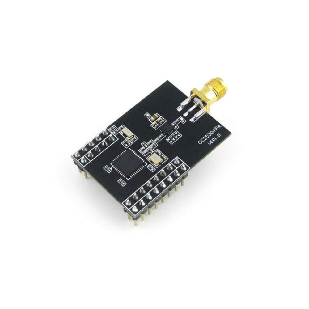
Main control chip: CC2530F256RHAR
Communication distance: communicable: over 1500 meters; reliable communication over 1300 meters; automatic reconnection: over 1000 meters (working environment: open area)
Working frequency band: 2.4GHz
Working voltage: 2.0V-3.6V
Temperature range: -40?ĕ?85??/div>


Serial port baud rate: 38400bps (default), can be set to other baud rate
Interface: All I/O interfaces except P1_1 and P1_4
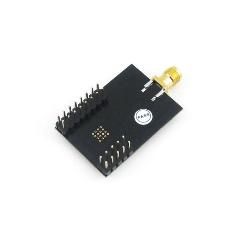
Interface spacing: pin spacing: 2.54mm; pin spacing on both sides 22.86mm (9x2.54)
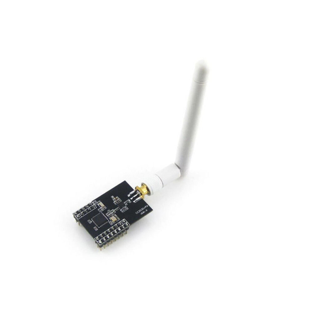
Antenna: Use 2.4G, 2DB omnidirectional antenna
CC2530F256 Core Parameters:
Working frequency band: 2.4GHz
16 transmission channels, switch reliable communication channels according to the environment
Wireless transmission rate up to 250kbps
High-performance, low-power 8051 microcontroller core
RF transceiver for 2.4GHz IEEE 802.15.4
Wide power supply voltage range (2.0ï½?.6V)
Watchdog, battery monitor and temperature sensor
12-bit ADC with 8 inputs
2 USARTs supporting multiple serial communication protocols, 1 infrared generating circuit
1 general purpose 16-bit and 2 8-bit timers
Advanced Encryption Standard (AES) coprocessor
21 general purpose I/O pins, 2 with 20mA current sink or current supply capability
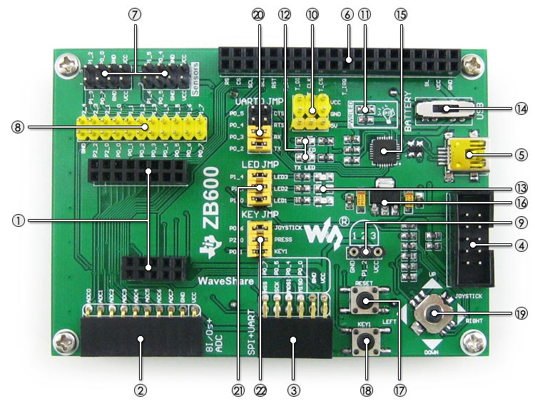
ZB600 baseboard introduction:
The onboard battery slot supports multiple power supply methods.
Lead out all IOs to facilitate user function expansion.
There is a CP2102 onboard, which is convenient for users to debug and update the program.
Onboard basic LED and buttons are convenient for users to operate.
The sensor interface is reserved for easy access to various sensors.
Package includes:
1 x ZB600 development board
1 x XCor2530
1 x 2.2inch 320x240 Touch LCD (A)
1 x AT45DBXX DataFlash Board
1 x Analog Test Board
1 x DS18B20
1 x Antenna
1 x USB cable type A male port to mini-B male port
1 x 4PIN+2PIN cable package


Interface:
1. Core board slot: easy access to Core2530 and XCore2530
2. Eight I/O+ADC interfaces: easy access to various modules using I/O control, such as 8-bit keys, motor control module, etc.
3. SPI+UART interface: It is convenient to access various modules using SPI interface and various modules using USART interface.
4. Debug interface: support download and debug
5. USB interface: After conversion onboard CP2102 USB TO UART chip, it is converted to UART.
6. LCD interface: easy access to 2.2inch LCD
7. Sensor interface: It is convenient to connect various sensor modules, such as temperature, humidity, gas and I/O connection with peripherals.
8. MCU pin interface: lead all pins to facilitate I/O connection with peripherals
9. 1-wire interface: easy access to 1-wire devices (TO-92 package). Such as temperature sensor DS18B20, electronic registration code DS2401, etc.
10. 5V and 3.3V power input and output interface: commonly used for external power supply, or common ground with user board
Device:
11. Power LED
12. Serial port transceiver indicator
13. User LED
14. Power switch
15. CP2102: USB to serial chip
16. AMS1117-3.3: 3.3V regulator device
17. Reset button
18. User buttons
19. Joystick: up, down, left, right, press, total 5 states
Jumper description:
20. UART0 JMP
21. LED JMP
22. KEY JMP
Instructions for using the above jumper:
Short jumper: access to the I/O specified in the sample program
Disconnect the jumper: you can use the cable to access the custom I/O instead


