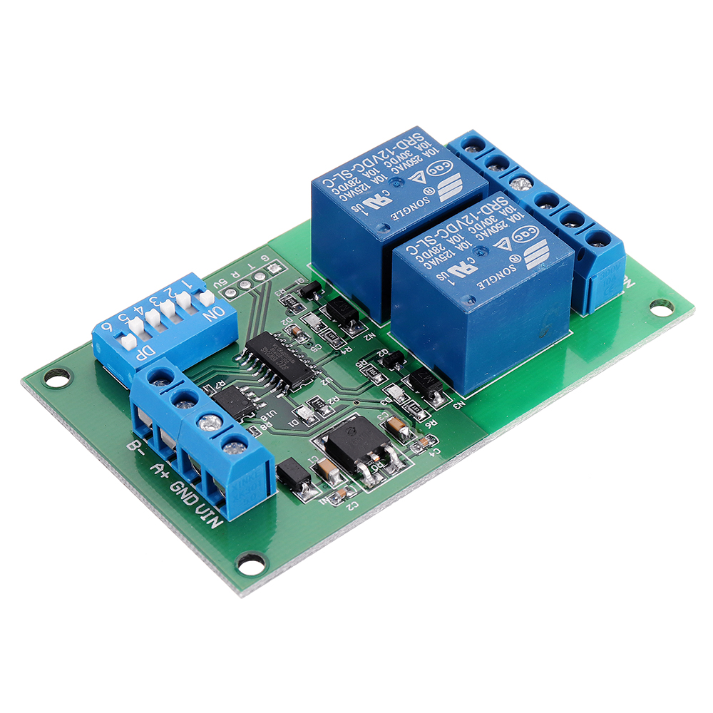
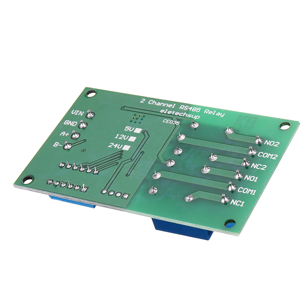
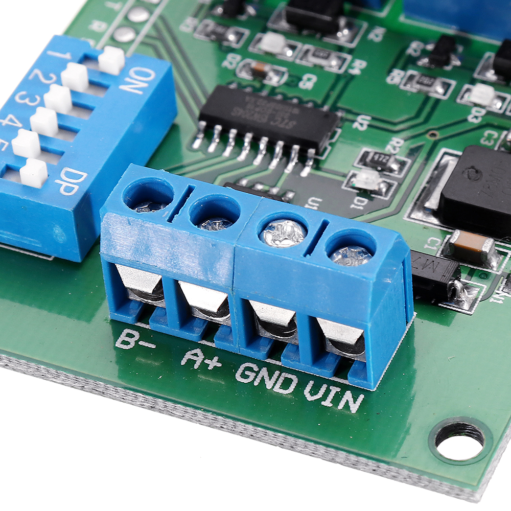
2 Channel RS485 Relay Board UART Serial Port Switch Module Modbus Remote Control for PLC Smart Home DC12V
Tax included.
>>>Manual: Click here to open<<<
Description:
Description:
- Power Supply: DC 12V
- Standby current (all relays closed) 7-8mA, 1 relay open 40mA, 2 relays open 73mA.
- "open" "close" "Momentary" "Self-locking" "Interlock" "Delay" 6 Commands
- Two instruction-control mode : AT command and MODBUS command
- Under the AT command ,the maximum delay is 9999 seconds,Under the MODBUS command ,the maximum delay is 255 seconds
- AT commands can be made serial HyperTerminal (serial assistant) Enter;MODBUS commands can be made serial HyperTerminal (serial assistant) OR "Modbus Poll" Enter;
- Under the MODBUS command mode, it can support up to 32 devices in parallel.
- Maximum load: 10A / 250VAC, 10A / 125VAC, 10A / 30VDC, 10A / 28VDC, 10A / 12VDC.
- Size: 79 x 47.5 x 19.5mm
Application:
Automated industry PLC;
Smart Home,Home Automation ,Wiser Home;
Identification system;
Motor FW & BW.
Typical Applications:
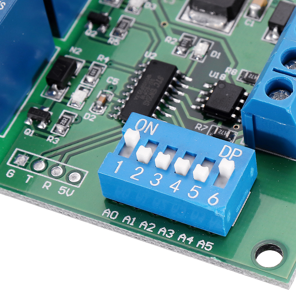
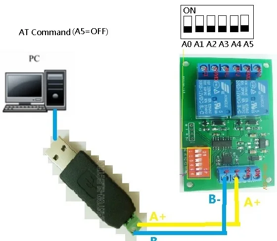
1. AT command mode (A5 = OFF), in this mode can be through the serial HyperTerminal (serial assistant) enter a simple AT command control relay. AT command mode time up to 9999 seconds
2. MODBUS command mode (A5 = ON), you can control a variety of ways: Serial Hyper Terminal Control (need to manually add the CRC), Modbus Poll software control (software automatically add the CRC), PLC or MCU process control


Wiring Diagram:
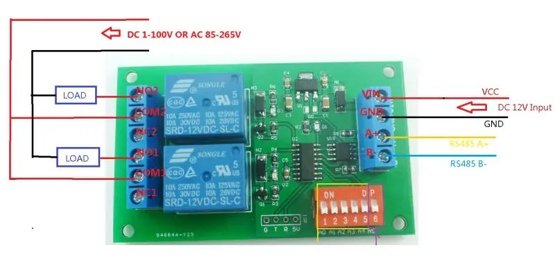
1. DC 12V control circuit,Wiring diagram below. "LOAD" may be camera,LED lights, fans, motors and other DC 12V equipment

2. DC 12V motor reversing control, Wiring diagram below. "LOAD" can be Fans, motors, pumps and other DC 12V equipment

3. DC 1-48V OR AC 85-265V control circuit,Wiring diagram below(Note:If not DC 12V load, need another DC 12V power supply). "LOAD" may be LED lights, fans, motors Lights, fluorescent lights, solar water heaters and other DC AC equipmen
4. DC 1-48V OR AC 85-265V control circuit,Wiring diagram below(Note:If not DC 12V load, need another DC 12V power supply). "LOAD" may be Machine tool ,CNC,3D Printer,LED lights, fans, motors and other DC AC equipment

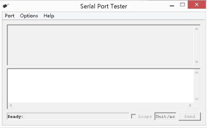
Test Software:
Serial HyperTerminal:
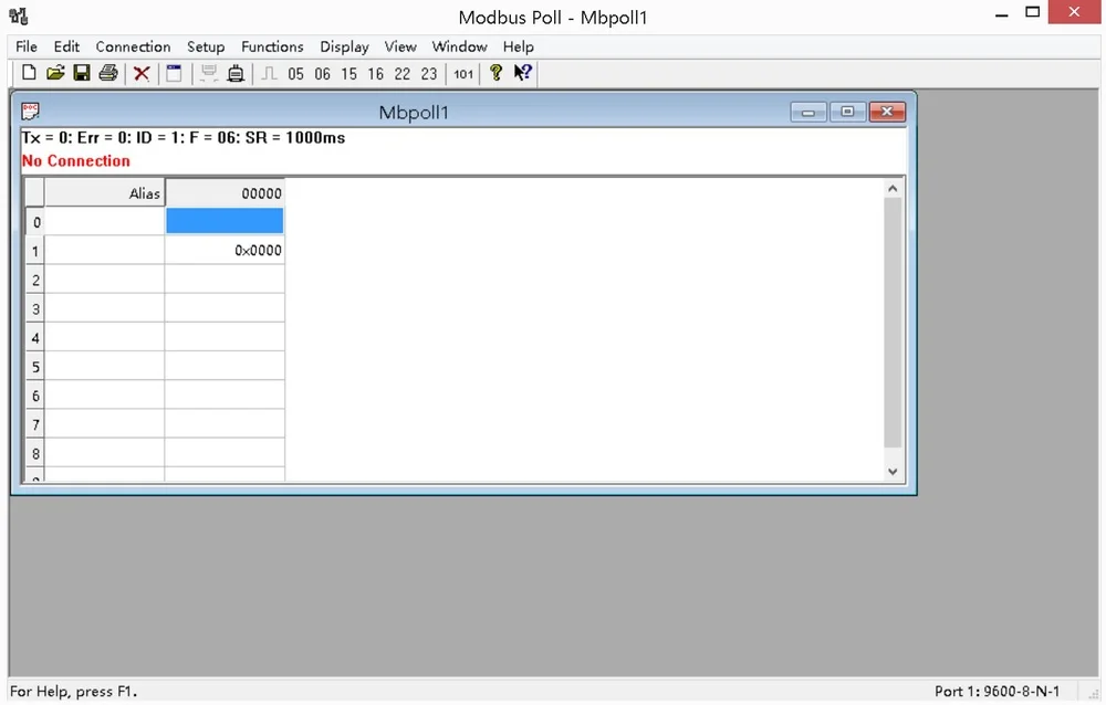
Modbus Poll
Package Included:
1 x 2 Channel RS485 Relay Board UART Serial Port Switch Module