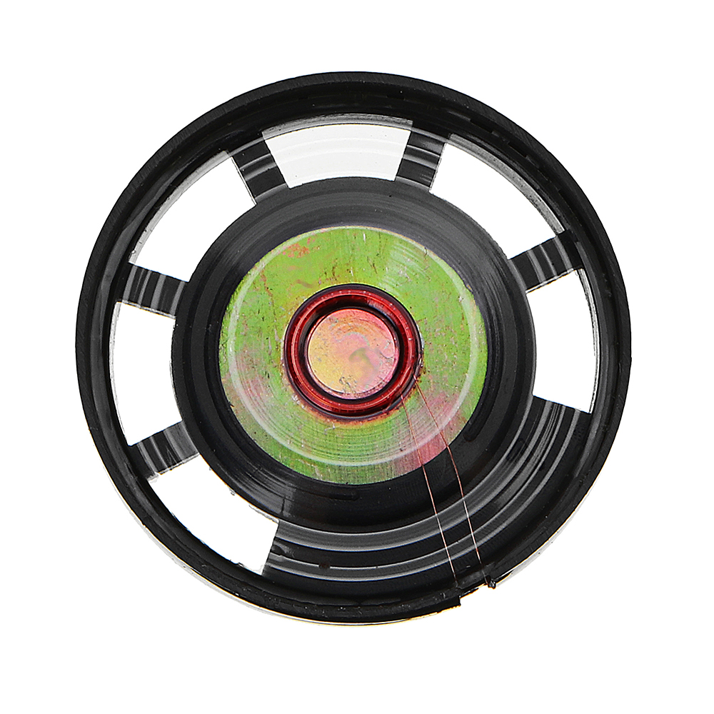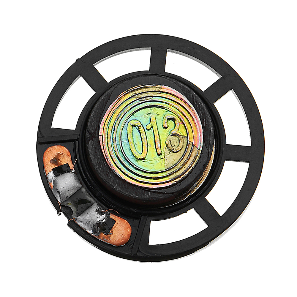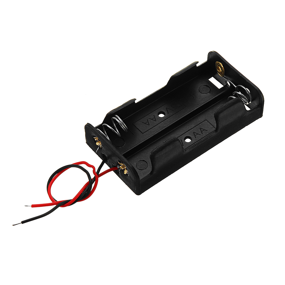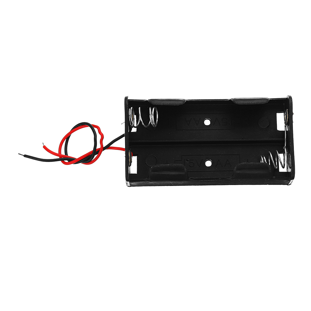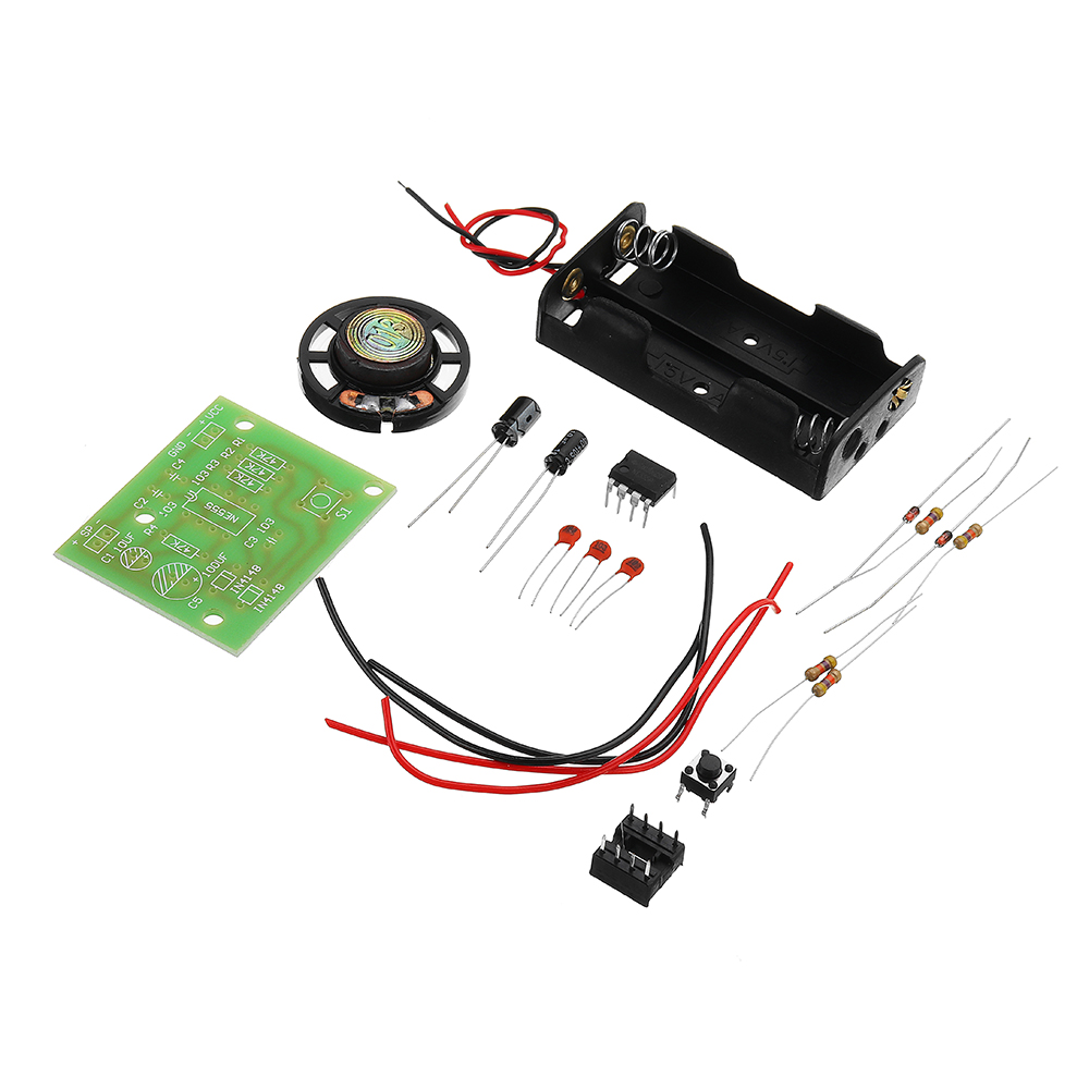
DIY NE555 Ding Dong Doorbell Kit Electronic Doorbell Module Kit
Tax included.
Description:
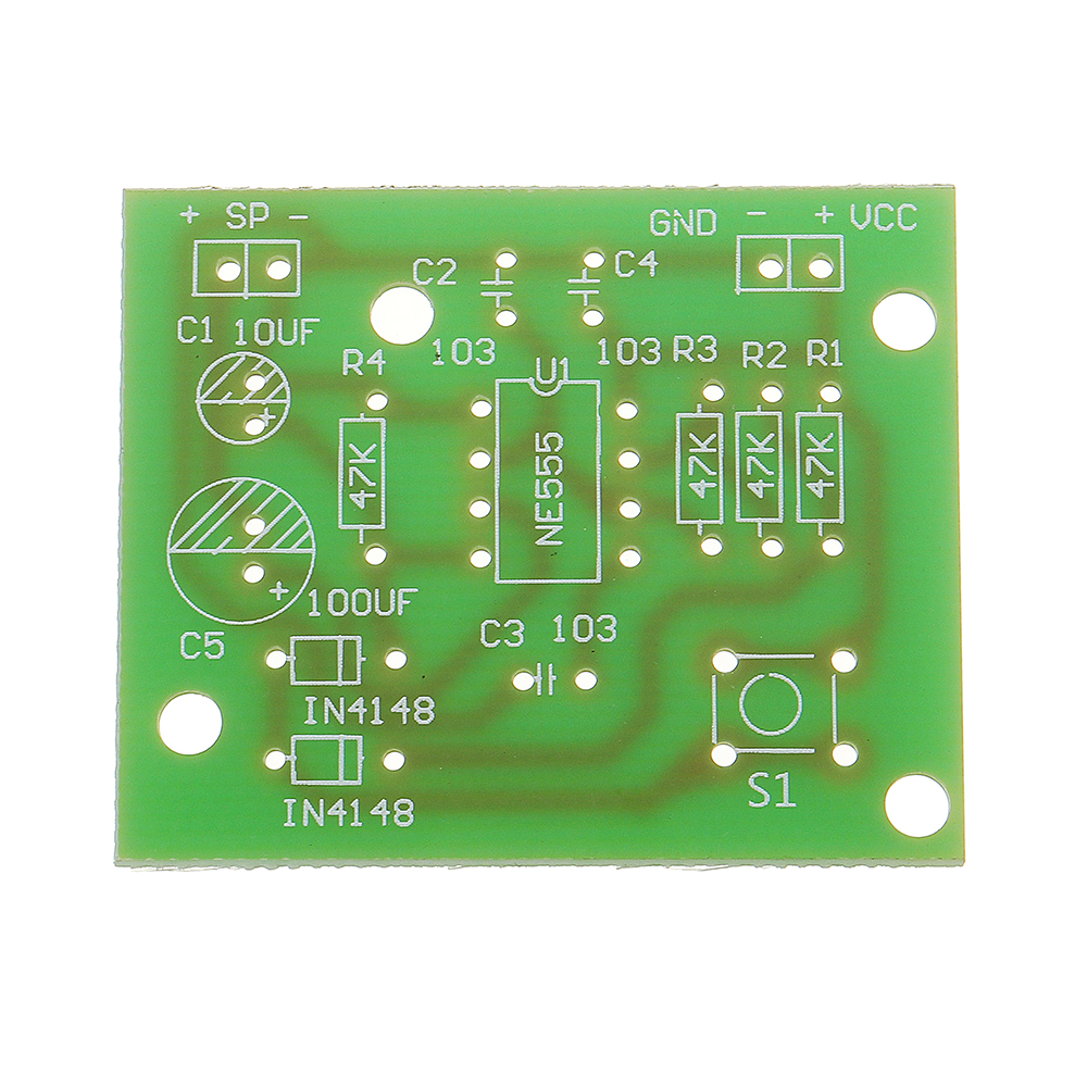
In the circuit diagram, NE555 and R1, R2, R3, D1, D2, C1 constitute a thank-you oscillator. S1 is a button switch that rings the doorbell. On weekdays, the button switch is disconnected. At this time, D1 is not turned on and D2 is turned off in reverse. So the fourth foot of NE555 is always at a low level. Because the fourth foot of NE555 is the reset end, when it is connected to a low power supply. Usually reset it, so 3 feet no output, loudspeaker does not ring. When S1 is closed, D1/D2 is conducting forward and C1 voltage rises. At this time, the lower 4 feet of NE555 are at high level, so it can not be reset. R1/R2/R3, NE555 and C3 constitute a thank-you oscillator. At this point, f=1/0.7 (R+2R2) C2 is approximately equal to 1013Hz (R is D2 and R2's resistance and is about 47K Euclidean). When SW is loosened, the charged C1 begins to discharge. R2, R3, C2 and NE555 form a thank-you oscillator. At this time, f = 1/0.7 (R1 + R2 + 2R3) C1 equals about 760 Hz.
Power Supply: 4 - 7V
Power Supply: 4 - 7V
Package Included:
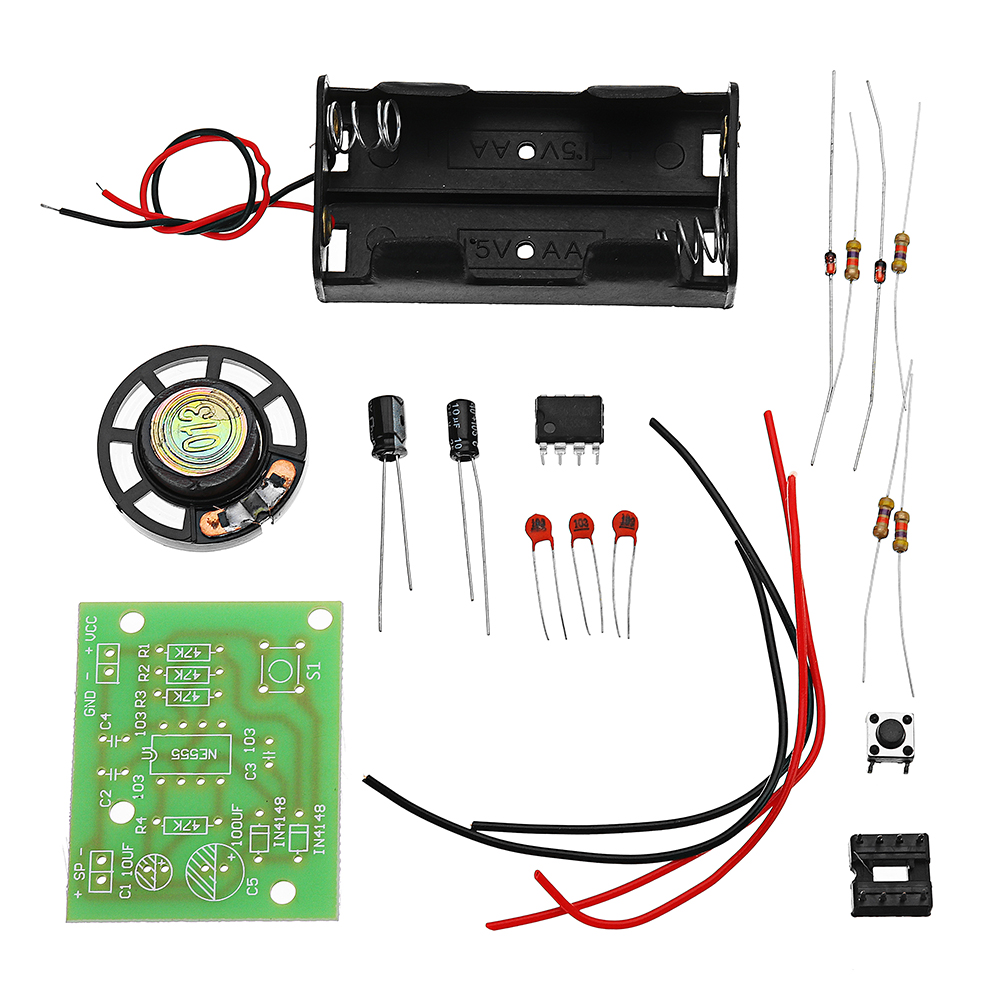
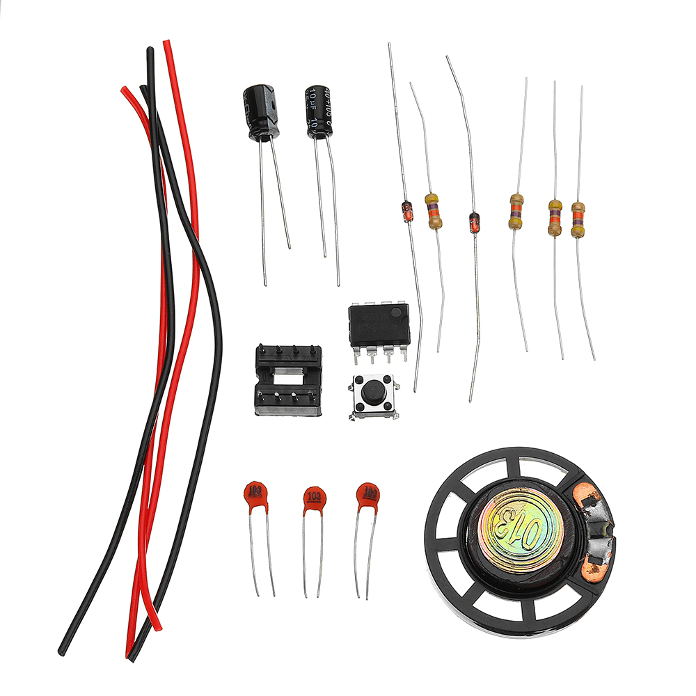
1 x DIY NE555 Ding Dong Doorbell Kit
1 x DIY NE555 Ding Dong Doorbell Kit

